|
NMR
This site is running |
NMR /
Receiver< Resistive probeheads | Index | Quick introduction to gtknmr >
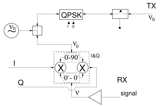
The inverted signal corresponds to a fixed phase shift of {$\pi$}. The purpose of this is phase cycling to cancel some of the electronics artifacts. The NMR signal, {$V(t)$}, duly amplified, is mixed with the reference {$V_0(t)$}. The ideal mixer performs a product of the two signals, and it is approximated by a suitable amplifier: {$V_{\rm out}(t)=V_0V\,\cos\omega_0 t\,\cos\omega t=\frac {V_0 V} 2[\cos(\omega_0-\omega)t+\cos(\omega_0+\omega)t ] $} Filtering out the high frequency term we obtain a signal, proportional to the NMR FID amplitude {$V$}, shifted down in frequency by {$\nu_0=\omega_0/2\pi$}. Note that the NMR response frequency is very close to the transmitter frequency, so that the difference is small. Quadrature detection is obtained by repeating the mixing twice in the dashed box (a minicircuit I&Q demod, with two replicae of the signal and of the reference. The latter is mixed directly on the right of the mixer and after a phase shift of {$\pi/2$} on the left. The phase shifted version corresponds to {$V_{\rm out}(t)=V_0V\,\cos\omega_0 t\,\sin\omega t=\frac {V_0 V} 2[\sin(\omega_0+\omega)t-\sin(\omega_0-\omega)t ] $} where, again, the low frequency part is proportional to the signal amplitude {$V$}. In general the phase difference between signal and reference is replicated in the down-shifted output of the mixer. The two slowly varying signals (we refer to them as audio frequencies, even if they may go up to 500 kHz) can be digitized with high resolution at moderate sampling rates. The ADC in HyReSpect works at or below 25 Msamples/s (a digital point for each phase every 40 ns). The digitized signals in the two channels (0 and 90 degrees) can be added to the content of two memory locations in the computer, to average out the noise. Problems and their heterodyne solution This scheme is fine for a spectrometer working at fixed frequency (e.g. for chemists using only one nucleus, say 1H at a fixed magnetic field). If the spectrometer must work at variable frequencies over a wide spectrum it is very inconvenient because there is no simple way of introducing a phase shift of {$\pi/2$} independent of the frequency it is applied to. The easy solution is called heterodyne (to be more precise, superheterodyne): it consists instead in phase shifting a fixed intermediate frequency and in using this frequency in a more complex mixing scheme. If the acquisition is started with the inverted oscillation (bit 1 set in the QPSK box) the audio signal will be inverted as well. In this case the audio output must be inverted again before adding in the PC memory. The net result is that the phase sensitive NMR signal adds up, whereas spurious systematic oscillations and baseline shifts generated in the electronics tend to cancel. < Resistive probeheads | Index | Quick introduction to gtknmr > |